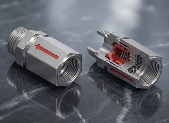
Stainless steel pulsation damper, whole and in section

pulsmin · since 2001 Pulsation dampers for compressors Protection against sudden pressure relief

Scroll down

Products

Pulsation dampers for two types of compressor and a pulsation dampening disc for reciprocating compressors

Both valves work on the same principle. For reciprocating compressors a damping disc is added against the discharge pulsation, marked blue in the sectional view. The pulsation dampening disc PDS is installed in the pipe between two flanges.

Screw and rotary vane compressors

PDV pulsation damper

You know the problem:

  • High oil content in the compressed air
  • Contamination of pipes and components with oil
  • Rupture of oil separator elements due to the pressure pulsation

The solution:

The PDV closes on a sudden pressure drop and holds the pressure upstream of the valve. The oil separator and compressor then work in quasi-steady-state operation.

To the PDV
Reciprocating compressors

PDV-DS pulsation damper with damping disc

You know the problem:

  • High oil content in the compressed air
  • Dryer granulate dust in pipes and components
  • Damage to reed valves

The solution:

In addition, the damping disc damps the discharge pulsation of the reciprocating compressor. pulsmin sizes the bypass bore and damping disc individually for every application.

To the PDV-DS
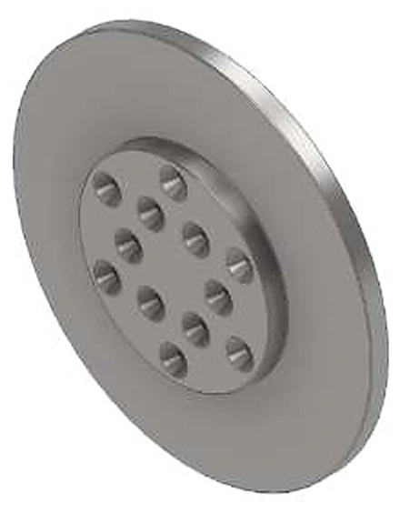
Pulsation dampening disc PDS with nozzle bores

Reciprocating compressors

PDS pulsation dampening disc

Efficient damping of gas pulsations in reciprocating compressors.

You know the problem:

Noise and vibration in pipes, fittings and the connected components.

The solution:

The pulsation dampening disc (PDS) offers a simple, compact and economically attractive solution.

To the PDS

The problem

System-induced pressure drops

Cause

Adsorption dryers switch between their cartridges in a fixed cycle (every 50 s up to several minutes). When the depressurised, regenerated cartridge is switched in, a physically induced pressure drop occurs in the main air flow.

System behaviour

  • Adsorption dryers with a pressure equalisation phase: Dampen the pressure drop by pre-compensating the pressure before switching over.
  • Standard air dryers without a pressure equalisation phase: Release the full chamber volume abruptly and undamped.
  • Compressor stop: Depending on the system design, the relief for the unloaded restart takes place either throttled via the suction line or abruptly via the dryer drain.

Physical effect

Undamped relief processes create pressure dips that travel back into the compressor at the speed of sound. The compressed air expands abruptly across the oil separator element and exposes the filter media and system components to an extreme dynamic alternating load.

  • Oil in the compressed air networkResidual oil content rises. Pipes, dryer and components are contaminated.
  • Ruptured oil separator elementsThe alternating pressure differences wear down the filter fleece until it tears.
  • Dust and valve damageWith reciprocating compressors, the discharge pulsation adds to this: dryer granulate breaks down into dust in pipes and components, and reed valves are damaged.

The solution: the pulsation damper valve (PDV)

The PDV slows the relief down to a rate the system can handle, gently dampens returning pressure peaks and reliably protects the oil separator element and the entire system against high material stress.

Schematic: compressor with oil separator, non-return valve, pulsation damper, adsorption dryer with idle and drain valve and silencer, non-return valve, tank, consumers Compressor Oil separator Non-return valve Adsorption dryer Idle anddrain valve Silencer Non-return valve Consumers Tank Pressure dip pulsmin
Installation point with an adsorption dryer, as specified in the operating instructions: between compressor and dryer, ideally directly in the compressed air inlet of the dryer. All parts upstream are then protected against the dryer switching. With membrane dryers the damper sits downstream of the dryer, in any case upstream of the relief valve.

How it works

1 · Normal operation

The valve is open.

The compression spring holds the piston off its seat. Air flows through the piston and past the seat; the flow loss is negligible.

2 · Dryer switching

The pressure drops downstream of the valve and the piston closes.

The air still being delivered can only pass through the bypass bore in the piston. It is sized so that operating pressure is held upstream of the valve.

3 · Pressure equalisation

At equal pressure the valve opens again.

The compressor, oil separator and upstream pipe keep working in quasi-steady-state operation. The valve works purely mechanically, without controls or adjustment.

Effect

Without PDV

Every time the dryer switches, the pressure drops sharply.

The line is vented abruptly. Afterwards the compressor has to refill the entire line including the dryer.

With PDV

Only a small pressure dip remains.

The valve closes as soon as the pressure behind it drops. At the compressor only an insignificant pressure drop remains; only the dryer has to be refilled.

Pressure after the compressor · schematic Pressure after the compressor over time, without and with PDVWithout a PDV the pressure collapses deeply every time the dryer switches and recovers only slowly. With a PDV only a small, short dip remains. The hatched areas are the energy loss areas. Pressure after the compressor Time without PDV with PDV
Schematic, after diagram 2 in the article in “Verkehr und Technik” 2016, issues 9 and 10, not to scale. Article (PDF, German)
Measurement report Rev. 02 · 19 January 2018

Measurement on a reciprocating compressor

Kötter Consulting Engineers measured the effect of a PDV-DS on an oil-free reciprocating compressor in a shunting locomotive. The pressures in the pipe upstream and downstream of the valve were recorded simultaneously.

Compressor
reciprocating, oil-free, two-stage
Intake volume flow
2,150 l/min at 1,579 min−1 (as stated by the compressor manufacturer)
Gauge pressure upstream of the PDV-DS
10 bar
Valve
PDV-DS G 1"
Sampling rate
2,000 Hz
Measured by
Kötter Consulting Engineers GmbH, Rheine
Pressure over time at measuring points P1, P2 and P3Upstream of the PDV-DS (P1) the pressure fluctuates between about 10.0 and 10.6 bar, downstream of the PDV-DS (P2) only between about 9.9 and 10.2 bar. The network pressure (P3) stays steady at about 9.8 bar. Pressure over time at measuring points P1, P2 and P3 (excerpt 630.575 … 630.675 s)Upstream of the PDV-DS (P1) the pressure fluctuates between about 10.0 and 10.6 bar, downstream of the PDV-DS (P2) only between about 9.9 and 10.2 bar. The network pressure (P3) stays steady at about 9.8 bar.
Pressure over time at measuring points P1, P2 and P3 at 10 bar gauge upstream of the PDV-DS. Redrawn from fig. 3 of the measurement report.
Pulsation upstream of the PDV-DS (P1)
0.604barpeak to trough
Residual pulsation downstream of the PDV-DS (P2)
0.254barAccording to the dryer manufacturer, less than 0.5 bar is sufficient to keep the desiccant grains from moving against each other, abrading and turning to dust.
Measured damping
40.3%excluding the share of the piping components in between, at 155 mbar pressure loss
Pulsation frequency
26.3Hzat 1,579 min−1
Damping rate of the PDV-DS as a function of the pressure lossThe damping rate rises with the pressure loss, from about 10 % at around 70 mbar to about 90 % at around 550 mbar. Pressure loss [mbar] Damping rate [%]
Damping rate of the PDV-DS as a function of the pressure loss (fig. 4). More damping costs pressure loss, for example about 60 % at around 280 mbar.

“Not as good as possible, but as good as necessary!”

Pressure profile in the compressor

Pressure dips with and without PDV

The diagrams show the pressure profile in the compressor of a compressed air system for rail vehicles during dryer operation: the pressure levels (holding points) during sudden pressure dips caused by the system-inherent dryer switchovers (regeneration/drying), without and with PDV.

Compressor
Screw compressor
Desiccant dryer
Twin-tower air dryer with pressure equalisation phase
Valve
PDV G 1"
Measurement location
Inside the compressor housing, downstream of the oil separator (clean side)
PDV installation location
Directly at the compressed air inlet of the dryer

a) Pressure profile in the compressor without PDV during dryer operation

Pressure profile in the compressor without PDV during dryer operationThe pressure rises to 10.5 bar. At each of the four dryer cartridge switchovers it drops abruptly to approx. 6 bar and then rises back to 10.5 bar. After shutdown it falls to 1.5 bar. Time [min] Operating gauge pressure [barg]Pressure [barg]
Pressure drop to approx. 6 barg, depending on the set pressure level during the pressure equalisation phase. For models without a pressure equalisation phase, the pressure drop is significantly greater. The depth of the pressure drop also depends on the buffer capacity (line volume, buffer tank) between the compressor and the dryer.

b) Pressure profile in the compressor with PDV during dryer operation

Pressure profile in the compressor with PDV during dryer operationThe pressure rises to 10.5 bar. At the four dryer cartridge switchovers it drops only briefly to 10 bar. After shutdown it falls to 1.5 bar. Time [min] Operating gauge pressure [barg]Pressure [barg]
Minimum pressure level with PDV: approx. 0.5 to 1 bar below the operating gauge pressure, regardless of the line volume.

Compressed air system with PDV

The system in 3D

Screw compressor with oil separator, combination cooler, fine filter, PDV directly at the inlet of the adsorption dryer, and main air reservoir – rotate it and zoom in. Switch the dryer over yourself, without and with PDV, and see what happens in the line.

View the system in 3D

Real-time 3D in the browser. The video demonstrates the physical effects of abrupt pressure drops when depressurised chamber volumes are connected to the main air flow without damping. How pronounced the returning pressure dip is depends on the upstream line volume (buffer effect) and on the degree of pressure pre-compensation in the regenerated chamber. The pressure curve runs along below the animation. With explanations in German and English.

Technical data

Operating range and material

The pulsation damper is not a maintenance item and needs no adjustment. pulsmin builds it to the volume flow and the required holding pressure. The pulsation dampening disc is designed for the operating point of the system.

Data sheet based on the operating instructions Rev. 00 and pulsmin data
PDV and PDV-DSPulsation dampening disc PDS
Medium and ambient temperature−60 to +140°C1)
Permissible operating pressure (gauge)20bar1)
Intake volume flowup to 4,000l/minNominal sizes G ½" (M 22×1.5), G 1" and G 1¼"1)
Pressure drop upstream of the valve when closingmax. 1 to 3barTest value for the function check after installation1)
Material of all partsStainless steel 1.4305Stainless steel 1.4305
Proven in service down to−50°CCompressed air systems for Russia1)
Mounting positionanyhorizontal to vertical, observe the flow direction1)
On the market since20012010

1) Depending on the design

References

In service

pulsmin pulsation dampers are found in compressed air systems of rail vehicles, metros, mountain railways and buses. A selection, with photos of the vehicles and installation points.

All references
Pulsation damper directly in the compressed air inlet of the dryer of a Class 146 electric locomotive, installation point marked red

DB Regio AG

Country
Germany
Use
Electric locomotive Class 146
Dryer
Air dryer LTZ 2.2-H
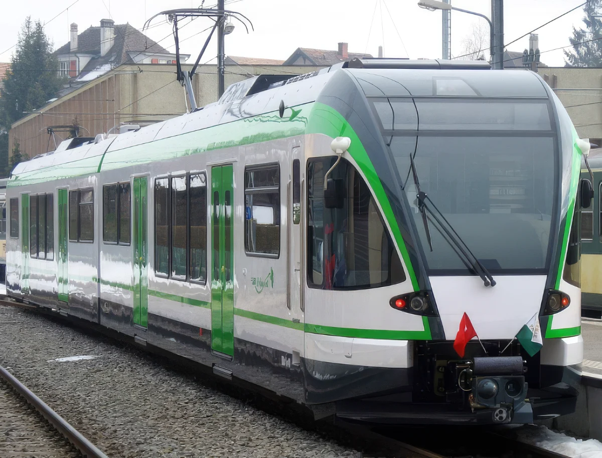
Green and white Stadler multiple unit at a platform

Stadler

Country
Switzerland
Use
Rail vehicles
Dryer
Twin-chamber adsorption
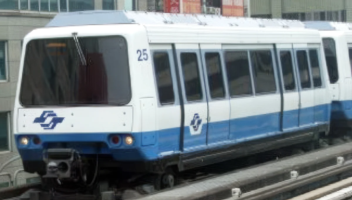
Taipei metro train, white with a blue stripe

Taipei

Country
Taiwan
Use
Metro
Dryer
Membrane
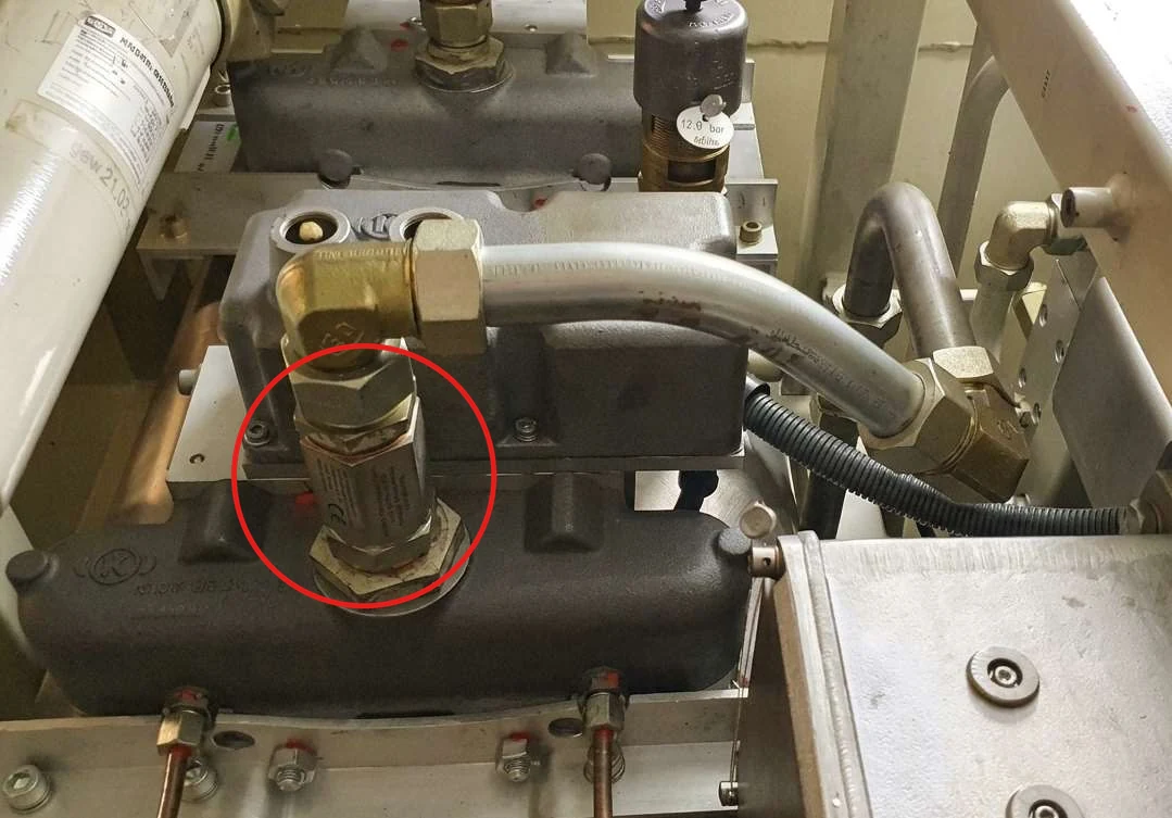
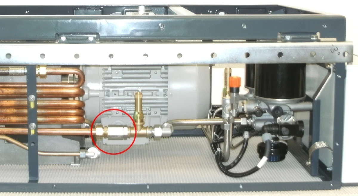
Compressor unit of the Matterhorn railway, installation point marked in red

Matterhorn

Country
Switzerland
Use
Mountain railway
Dryer
Twin-chamber adsorption
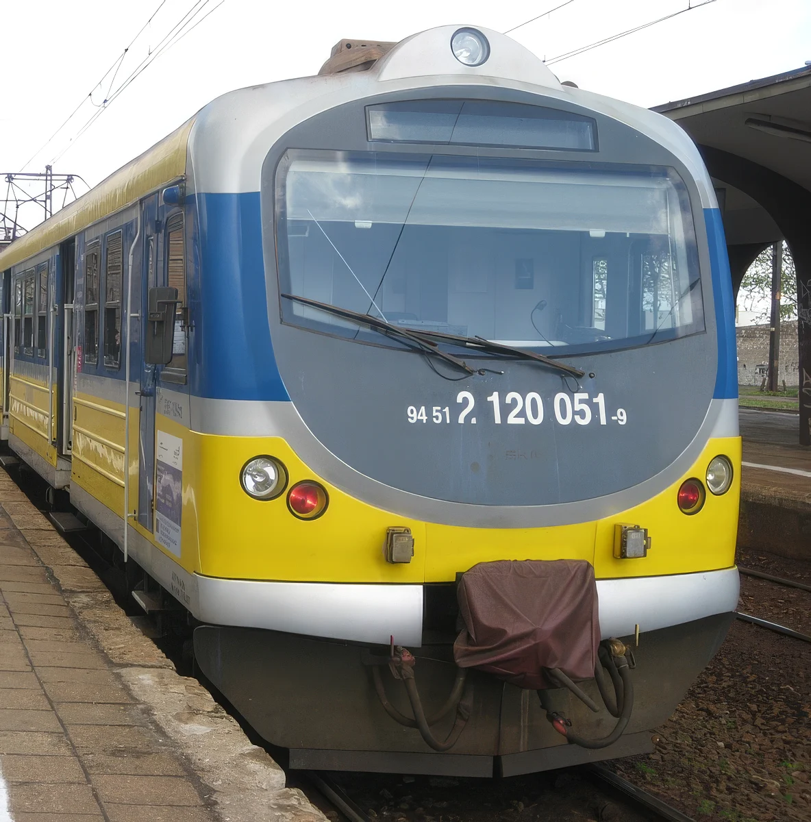
Yellow and blue SKM Trójmiasto multiple unit

SKM Trójmiasto

Country
Poland
Use
Rail vehicle
Dryer
Twin-chamber adsorption
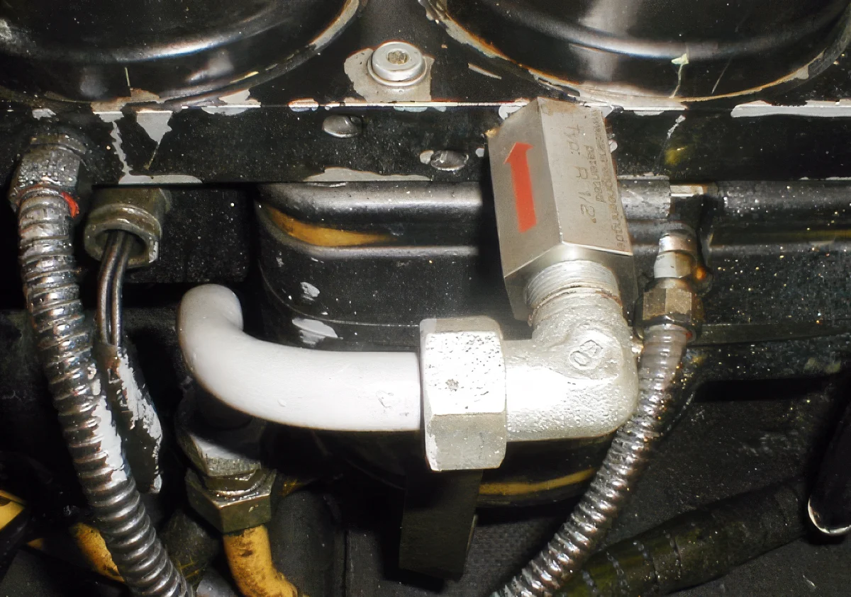
Installed pulsmin damper with red flow arrow in a Zagreb tram

Zagreb

Country
Croatia
Use
Tram
Dryer
Twin-chamber adsorption
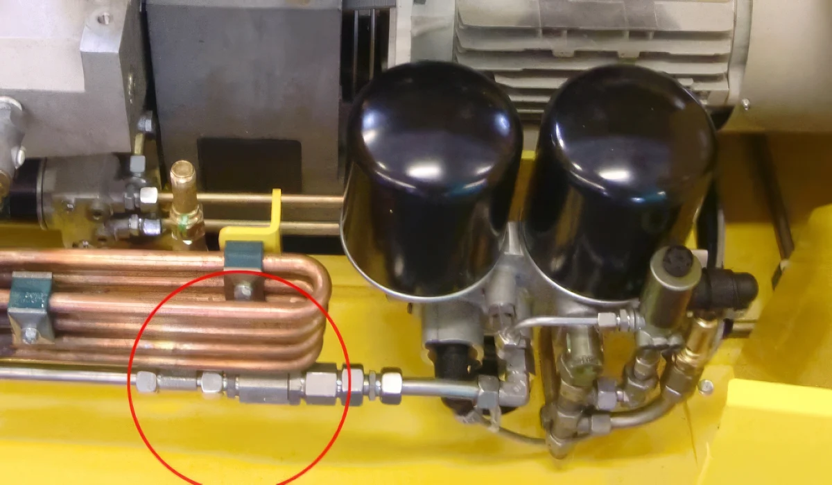
Yellow compressor unit of a Zagro shunting vehicle, installation point marked in red

Zagro

Country
Germany
Use
Shunting vehicle
Dryer
Twin-chamber adsorption
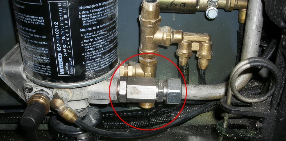
Compressed air treatment of an electric bus, installation point marked in red

Electric bus

Use
Bus
Dryer
Single-chamber adsorption

Background and measurements are described in the trade article reprinted from “Verkehr und Technik” 2016 (German). All documents